


MSC Sparkle Co
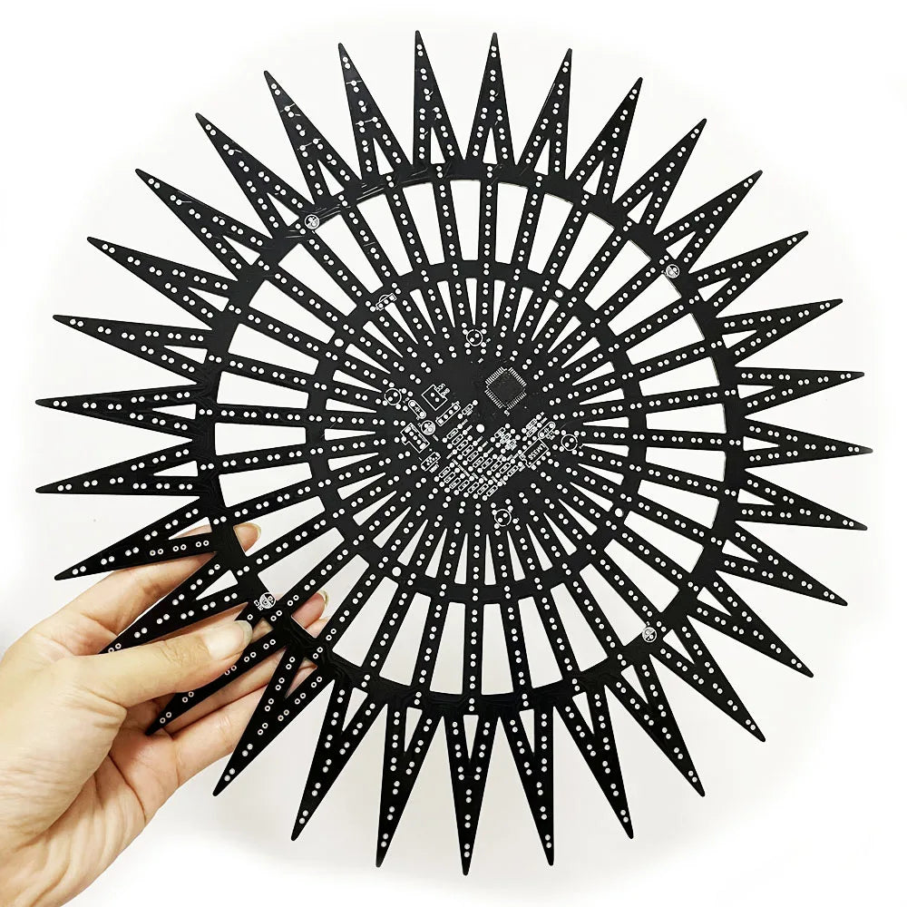
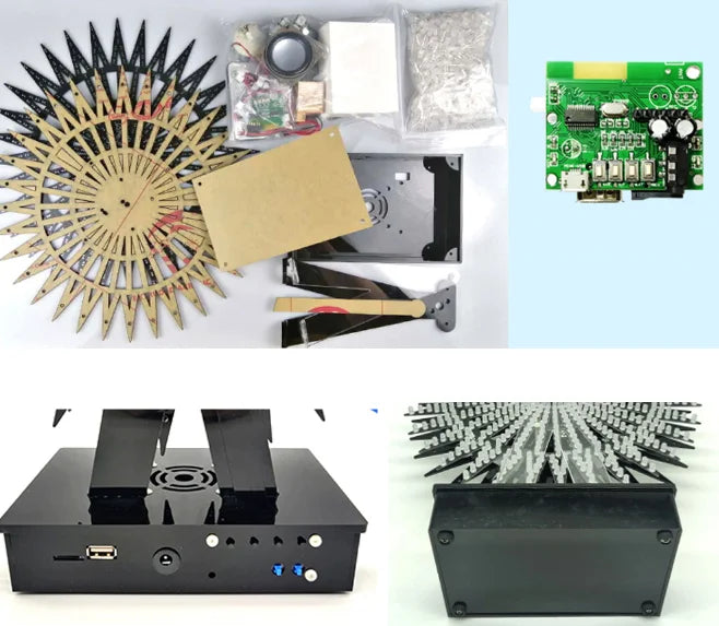
DIY electronic kit LED rotating ferris wheel (not assembled)
DIY electronic kit LED rotating ferris wheel (not assembled)
Couldn't load pickup availability
SPECIFICATIONS
Brand Name: NoEnName_Null
Hign-concerned Chemical: None
Model Number: 616748
Origin: Mainland China
Subject: PHYSICS
Please read before purchasing:
The installation of this kit is complicated. you can contact us for detail tutorials before pay, to make sure you understand the circuit work princeple .Please ensure that you have soldering experience and familiar circuit knowledge. Before purchasing, please turn to the tutorial at the bottom of this page to read it and make sure you can complete it.
As a seller, we can only guarantee that the products are complete and work with components, tutorials and technical support. There is no guarantee that every buyer will be 100% successful. Please do not malicious disputes cause by personal soldering technology problems .
Provide technical support and soldering tutorial!
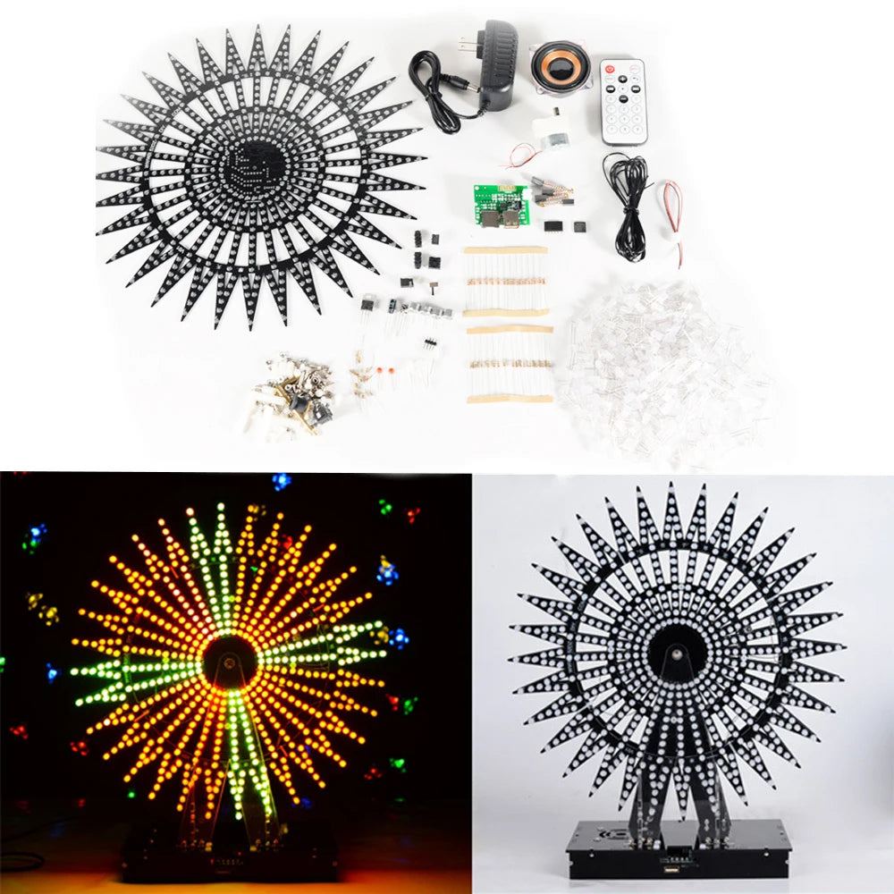
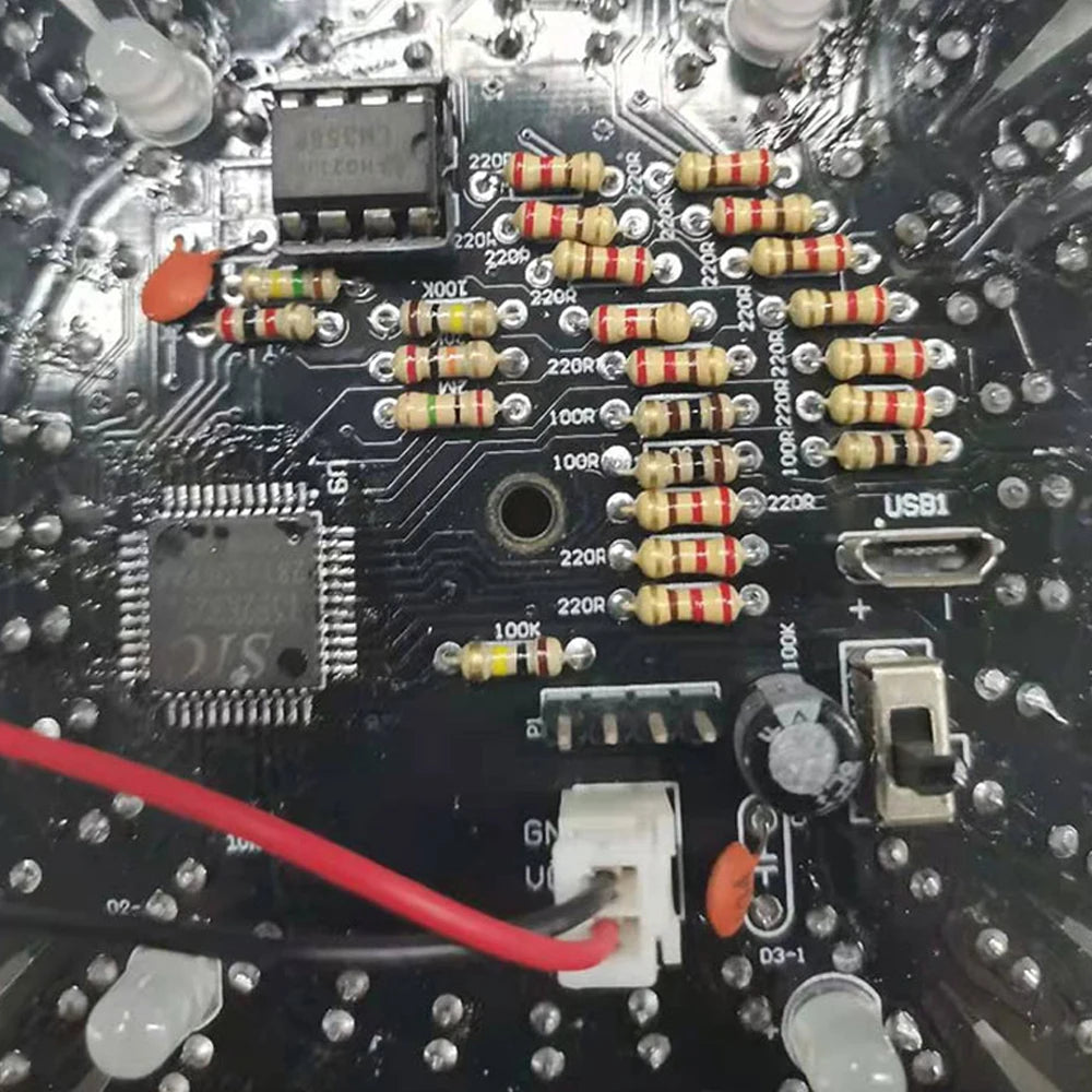
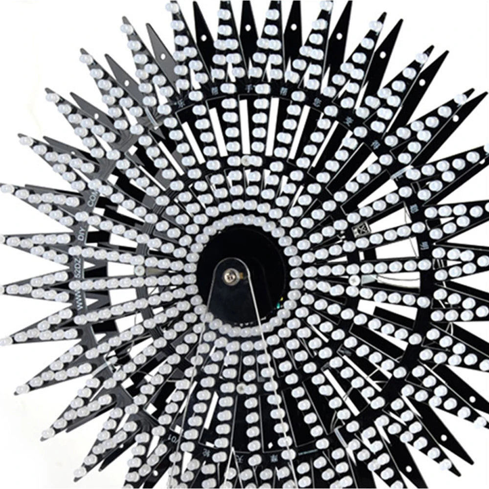
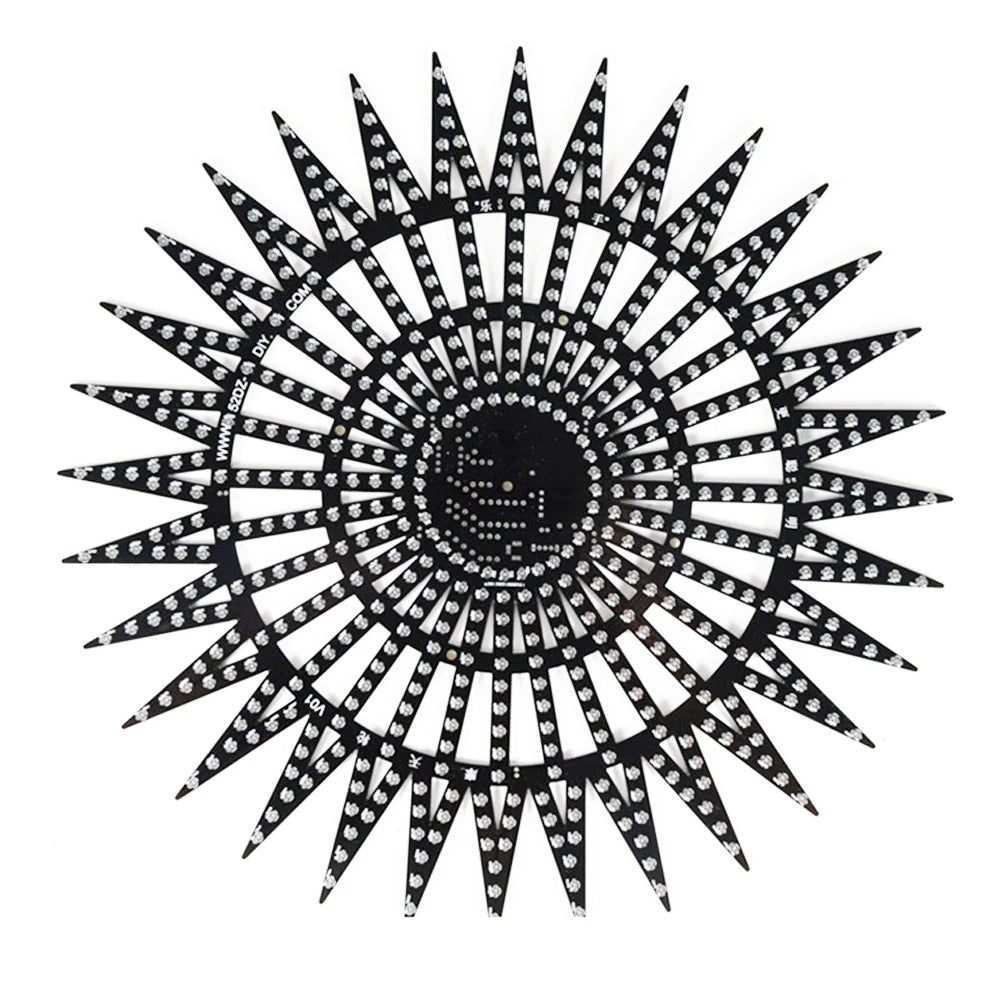
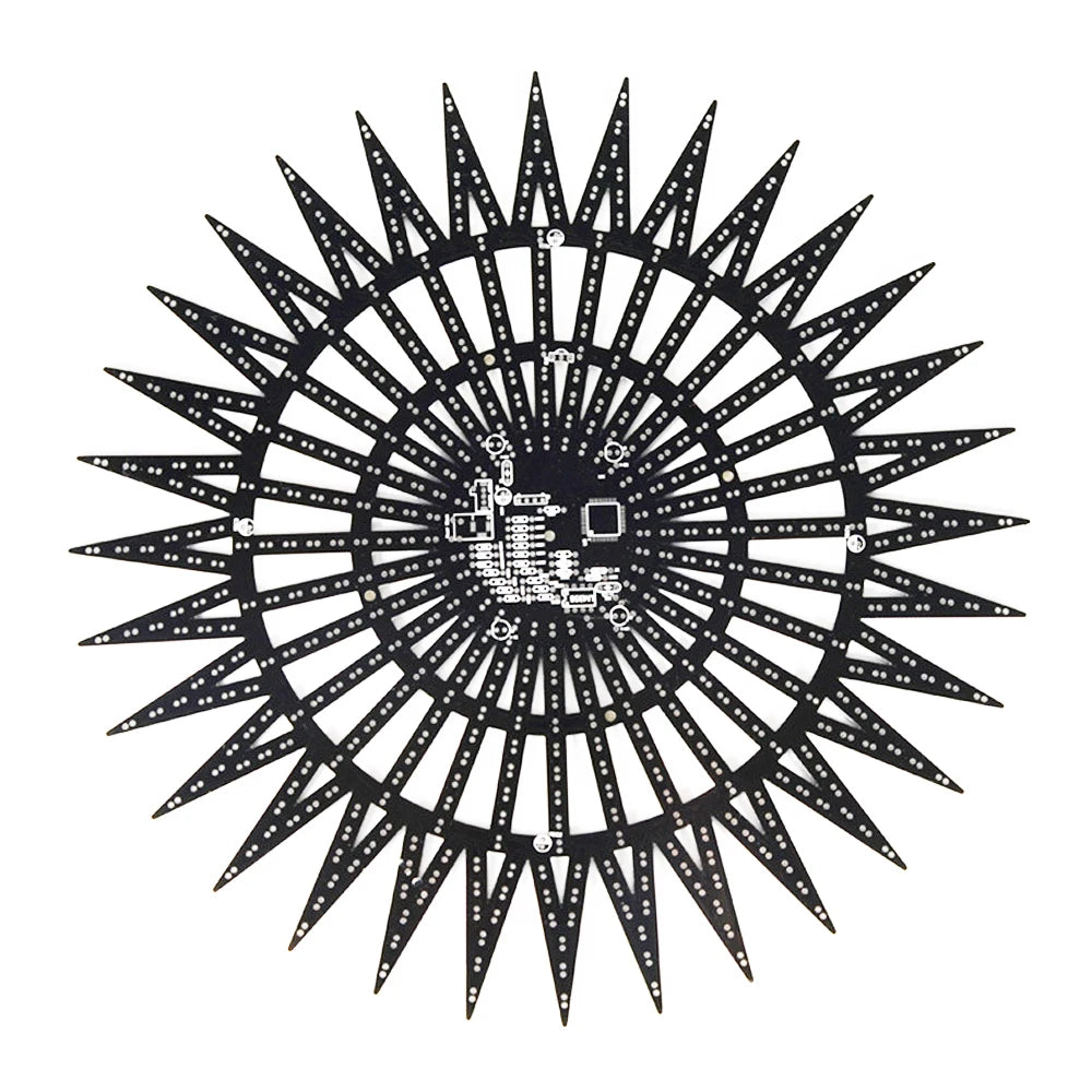
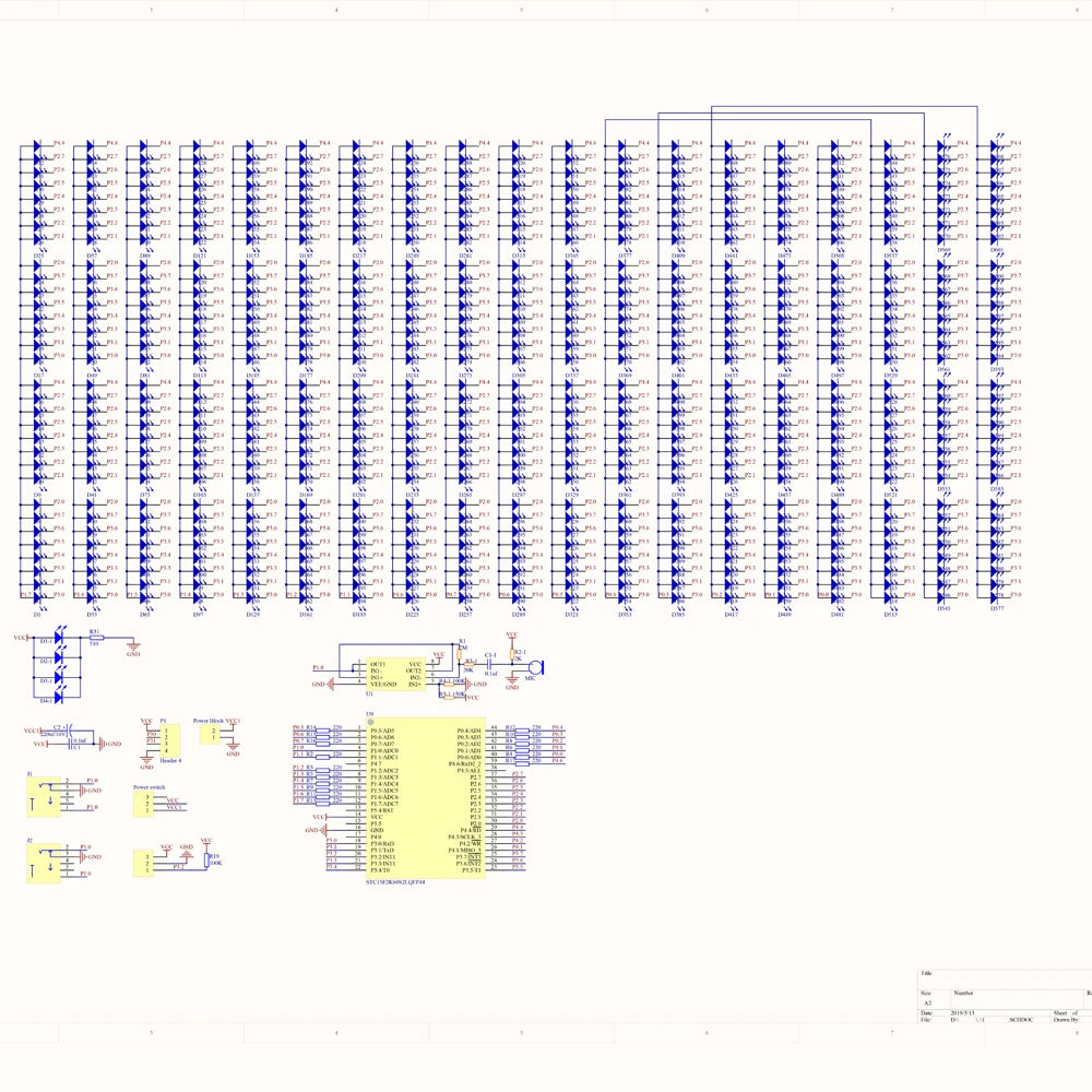
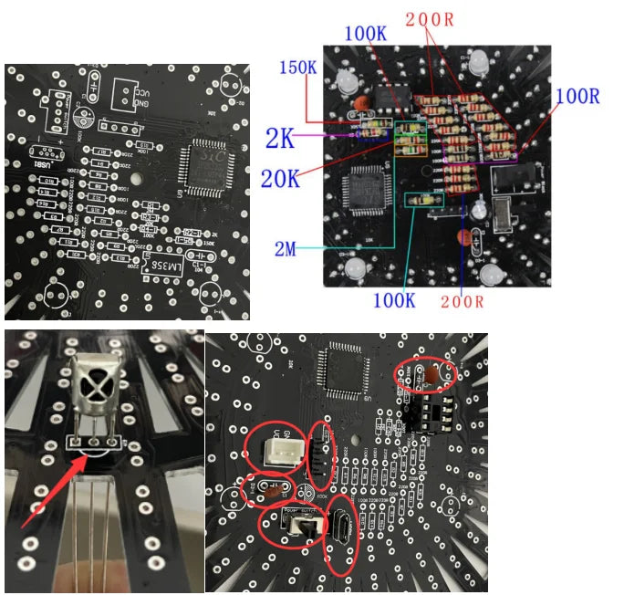
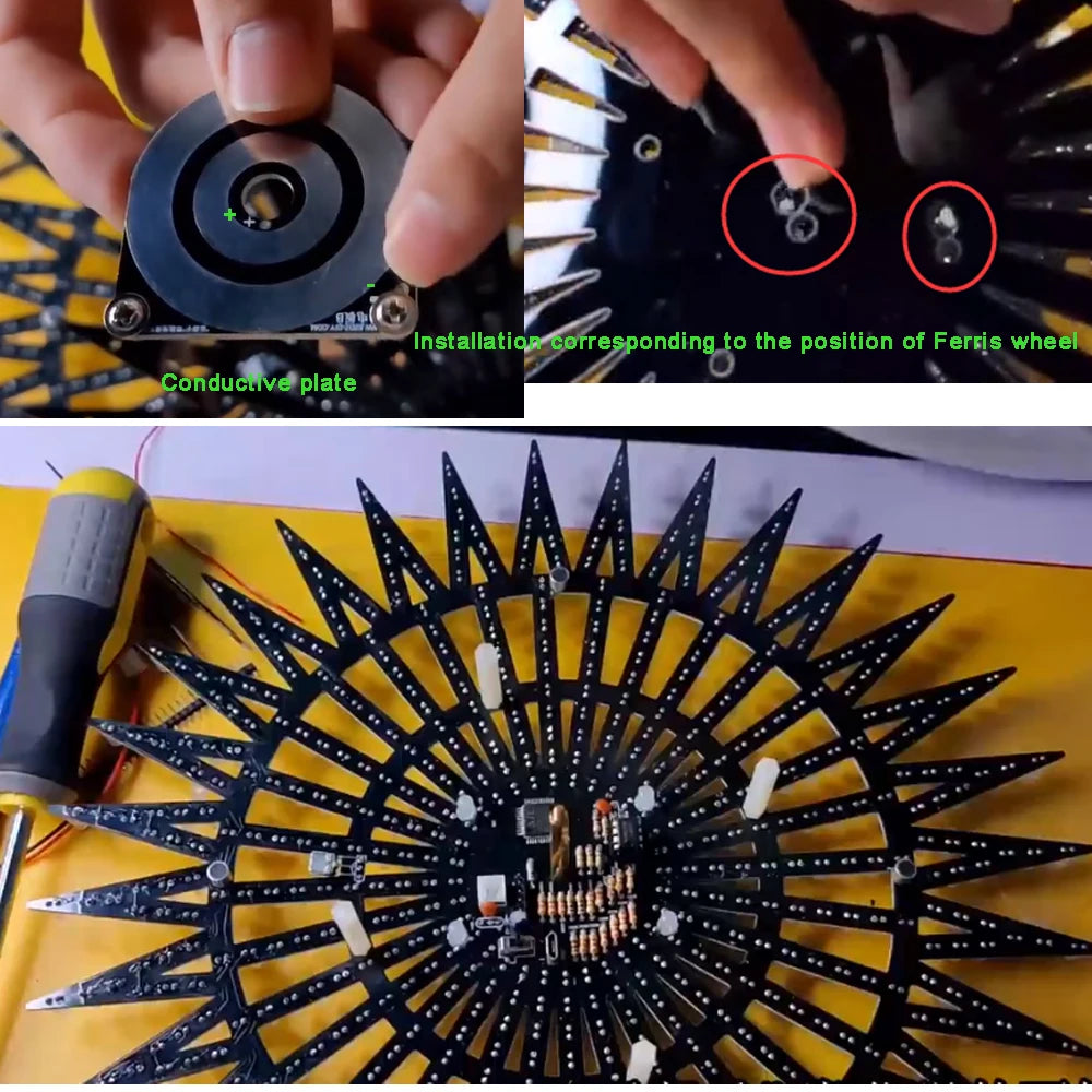
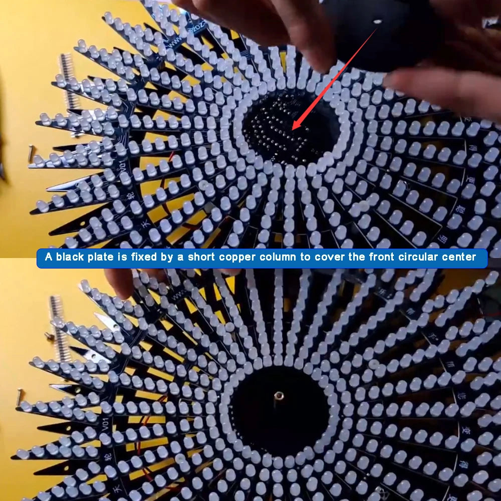
The components of the PCB are basically plug-in components, except for the main chip, which are soldered on the back of the PCB, The LED is soldered onto the front of the PCB. After welding, use 5V voltage to test the PCB part. You can use the remote control to test whether all the light beads in each turn are on. If there are any damages, replace them.
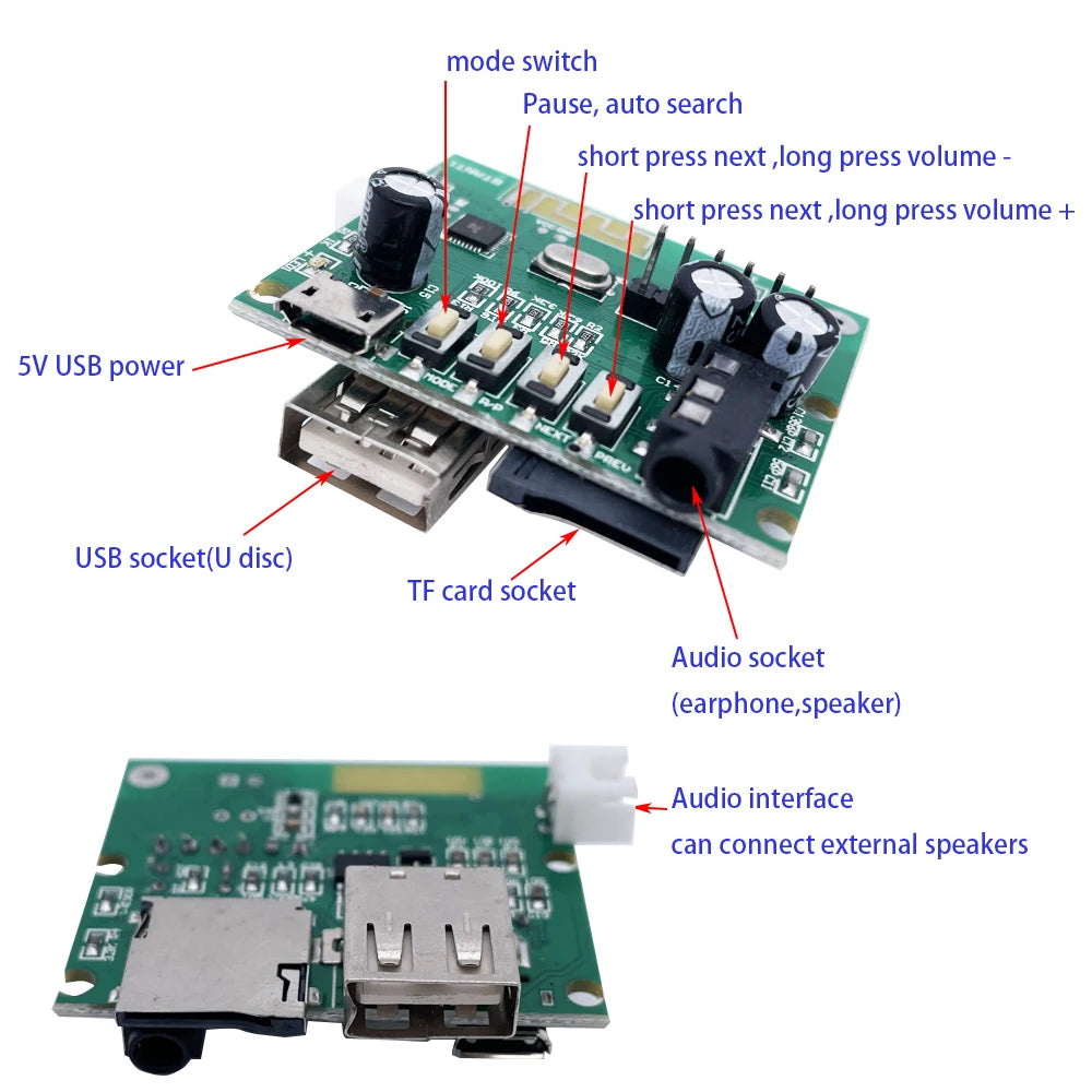
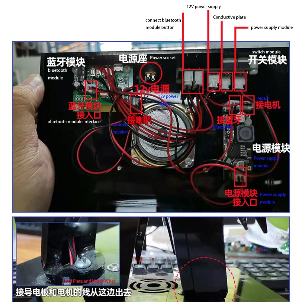
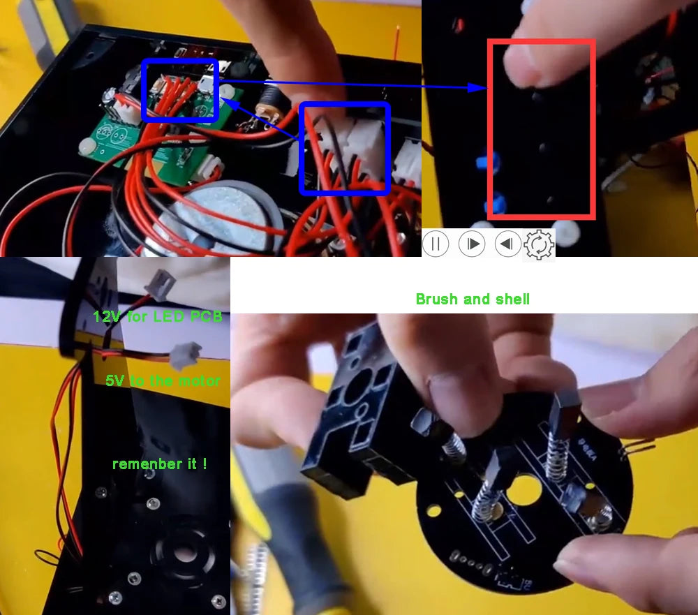
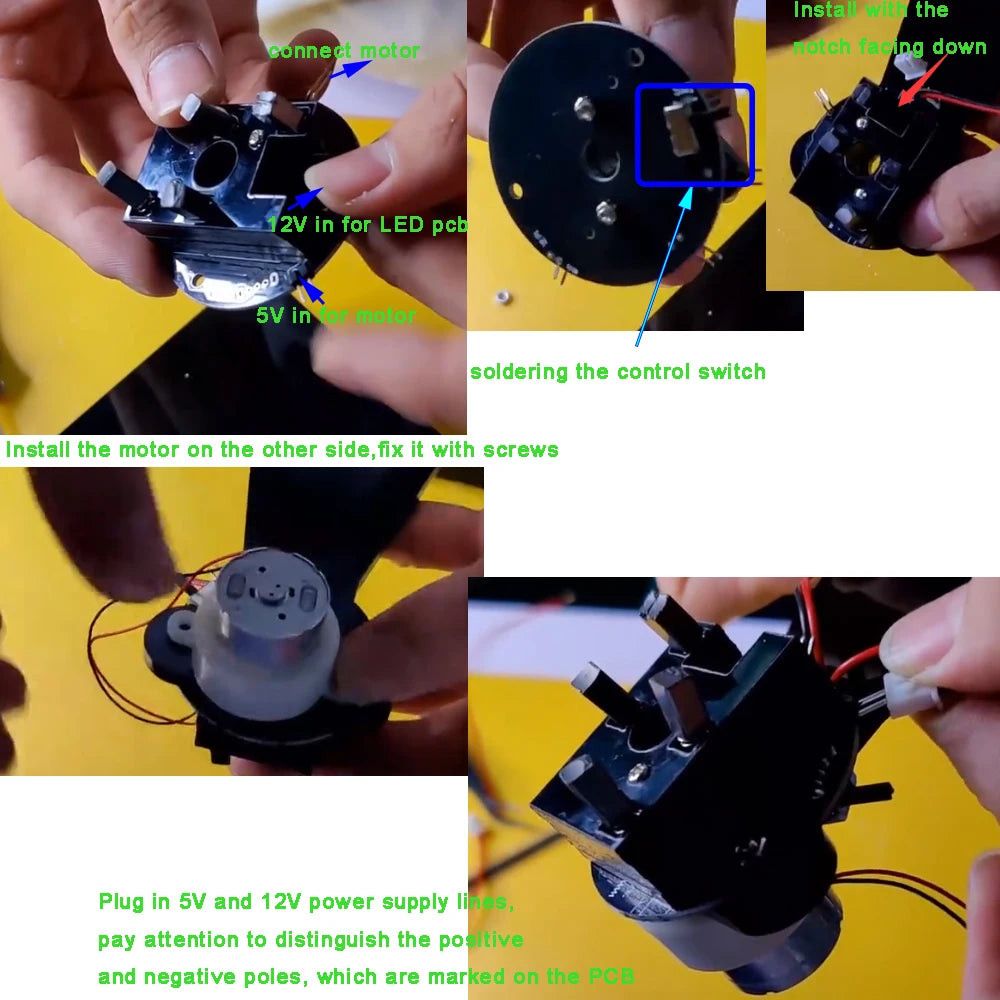
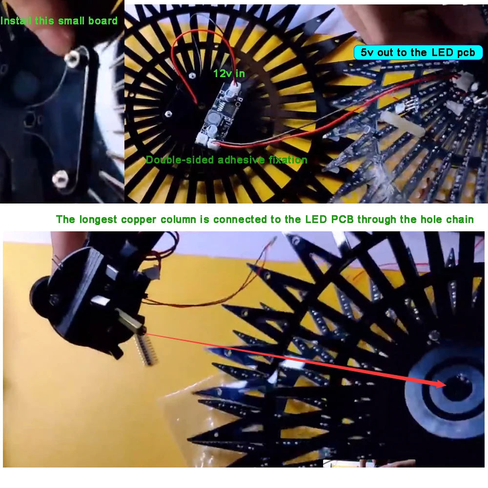
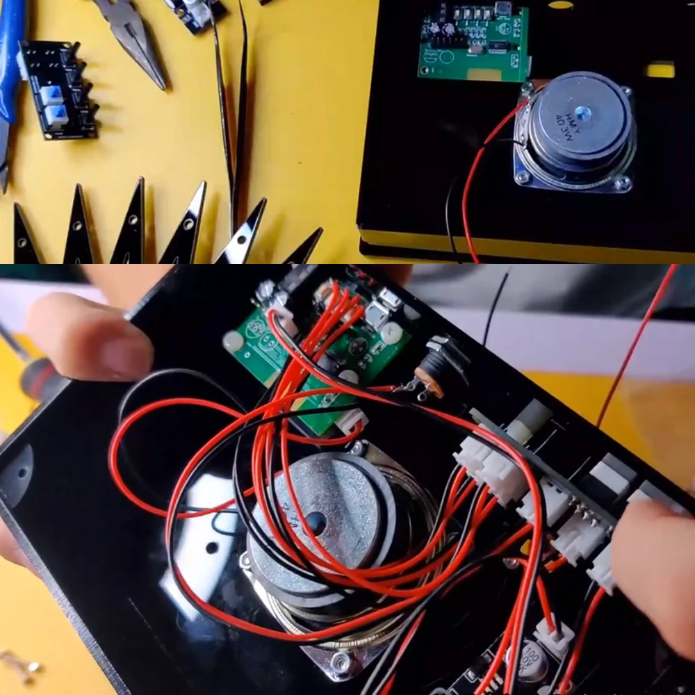
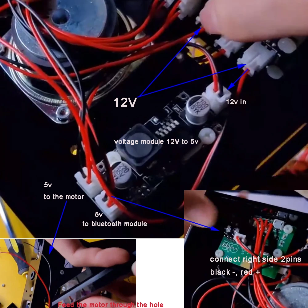
The base needs to be equipped with a Bluetooth amplifier module, soldered speakers, and switch modules. Due to the supply voltage being DC12V, the product is equipped with two DC12V to 5V voltage reduction modules that divide the 12V power supply into the Bluetooth amplifier module and PCB through a switch module. Pay attention to understanding the working principle and power supply parameters of each module.
Feature:
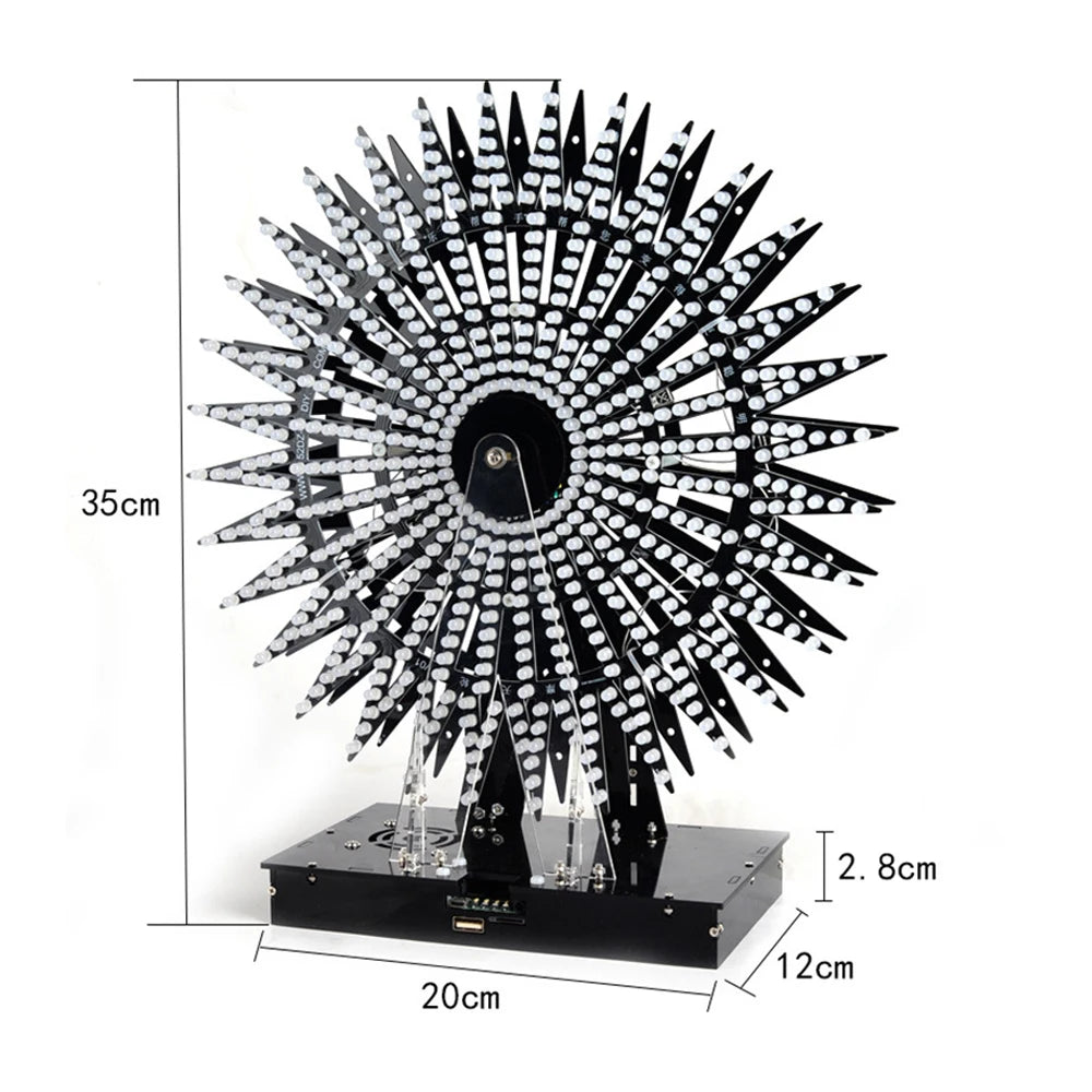
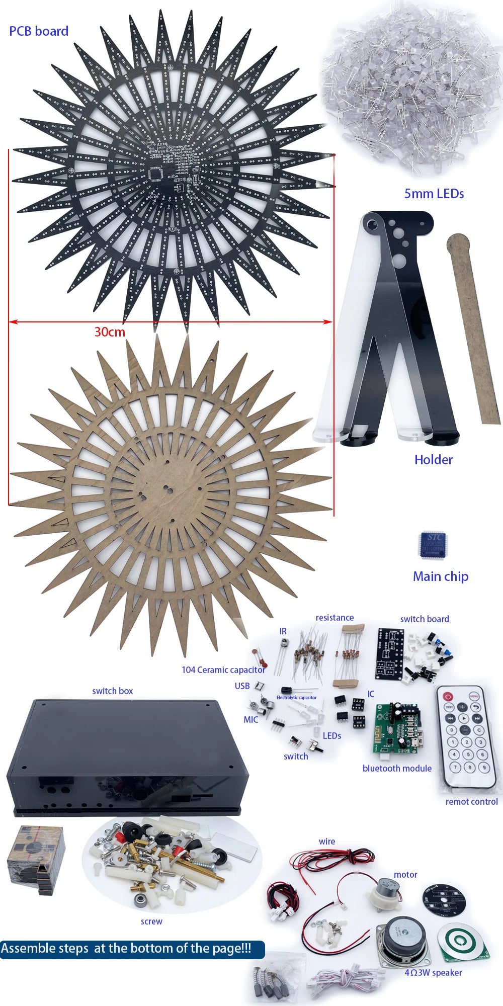
1. PCB size: 30cm;
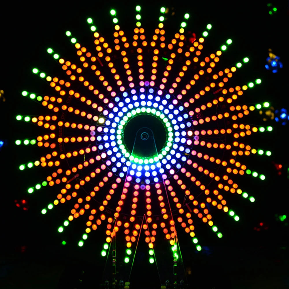
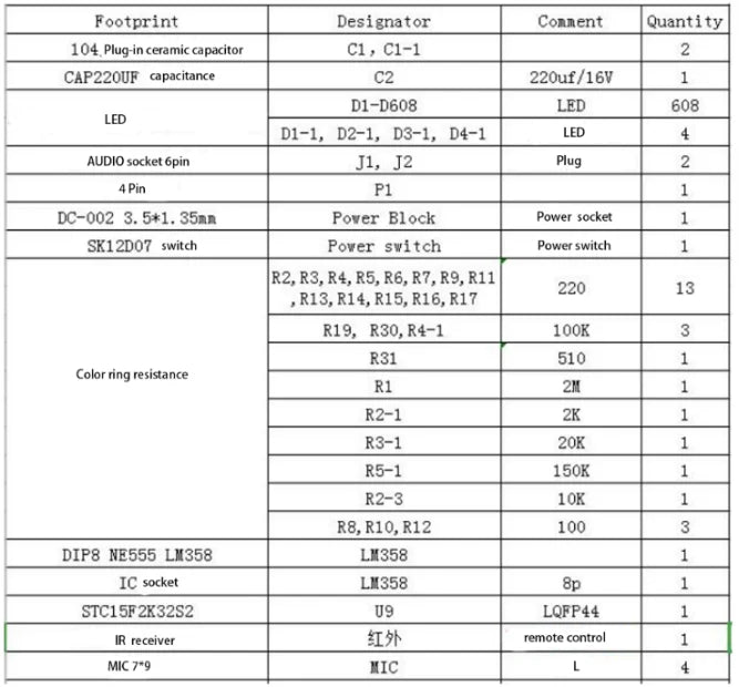
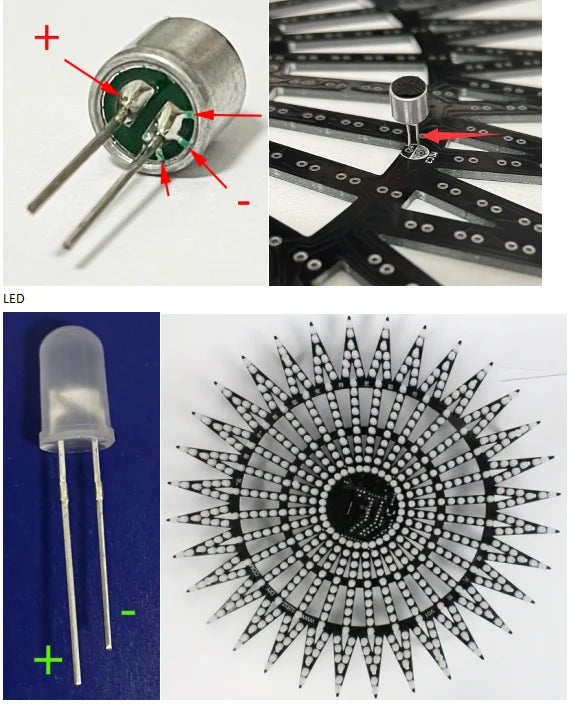
2. 610pcs 5mm colorfule LED ;
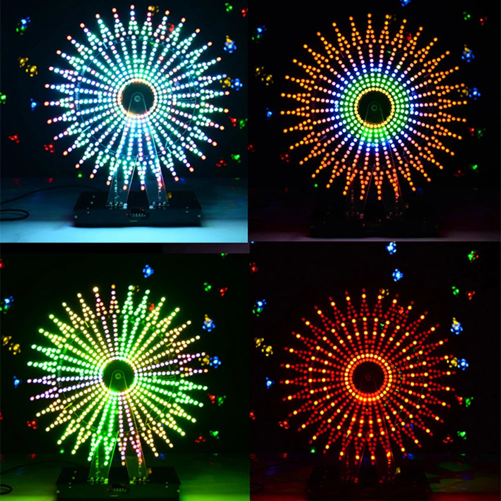
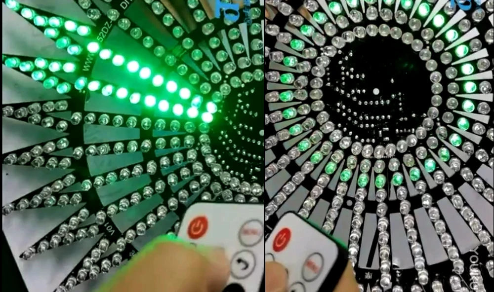
3. 7 Kinds music spectrum;
4. Bluetooth APP function, wirless play, TF,USB play.
5. 21 kinds flashing mode;
6. 16 layer LEDs
7. package size: 32x32x6cm 1.4kg


Installation tutorial


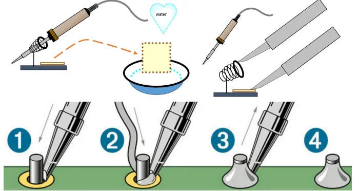
2. Welding tool preparation
Commonly necessary welding test tools: soldering iron, component box, multimeter, tin wire, tweezers, soldering iron stand, solder suction device, sponge, cutting pliers, needle-nose pliers, screwdriver, rosin flux, etc.

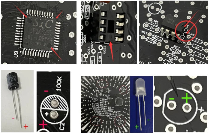
2. Component welding and installation
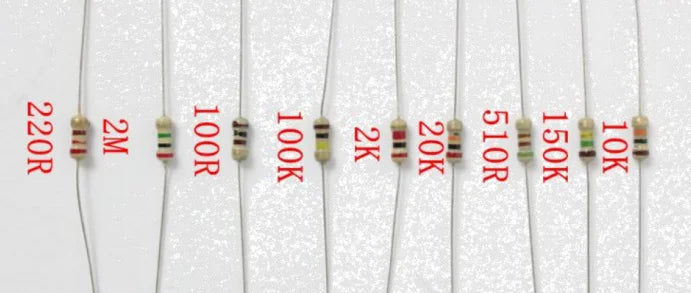
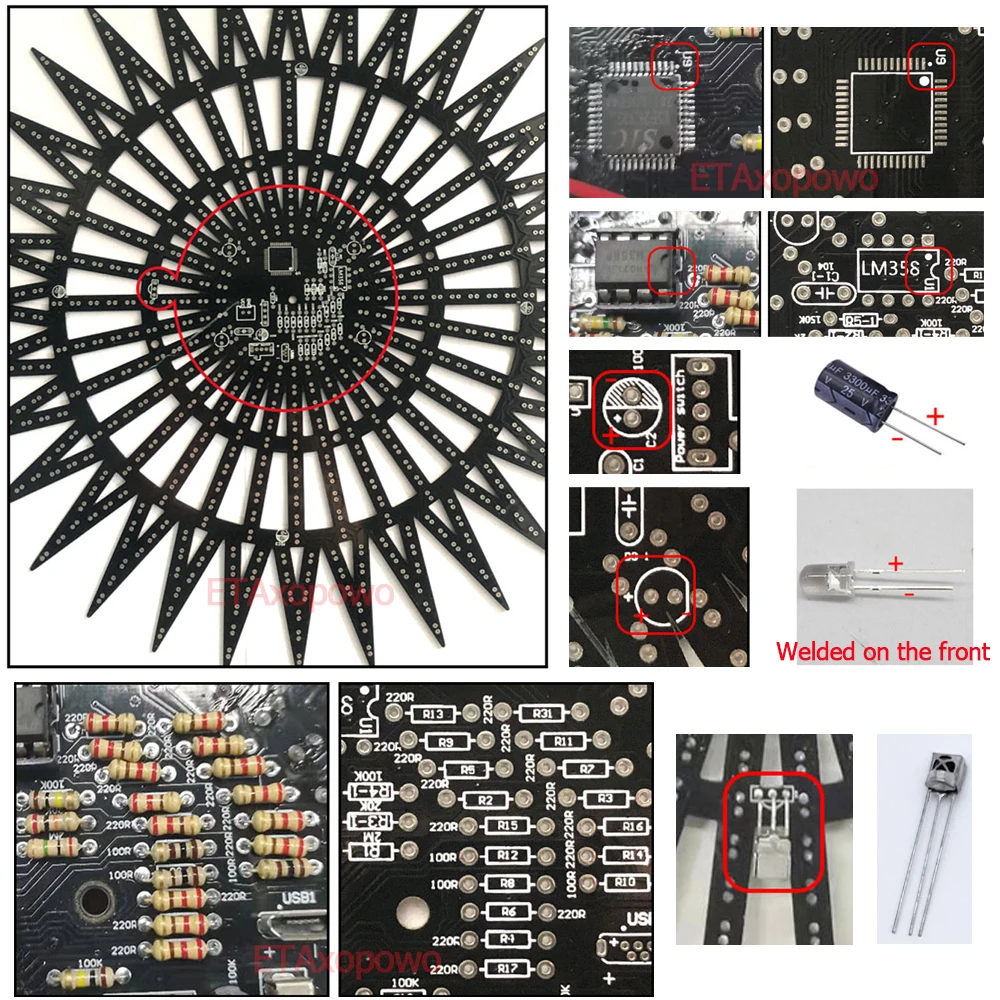
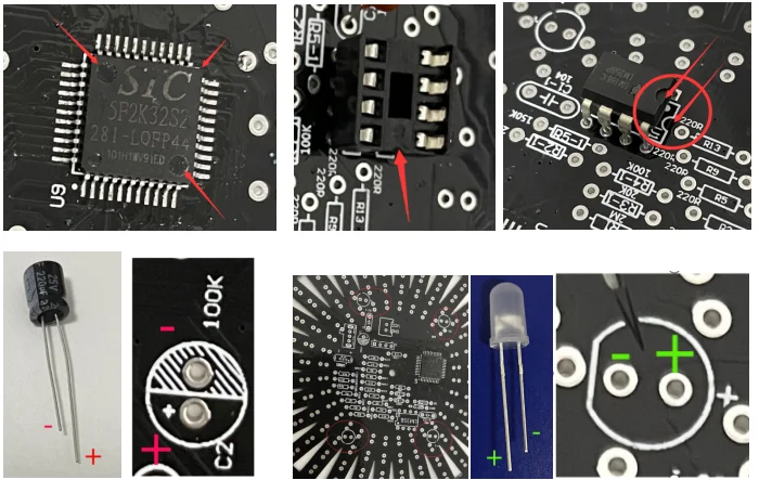
Before welding, use a multi-meter to measure the resistance value of the resistance. The polarity of capacitors and diodes should be distinguished before welding. Once the soldering is wrong, it must be carefully heated with a soldering iron and then removed and re-soldered. The down movement should be light. If the installation hole is blocked, use a needle to open it while heating. The reading direction of the resistance should be consistent. If the color circle is not clear, use a multi-meter to measure the resistance before installing. When attaching screws and nuts, the force should be appropriate, not too much force.


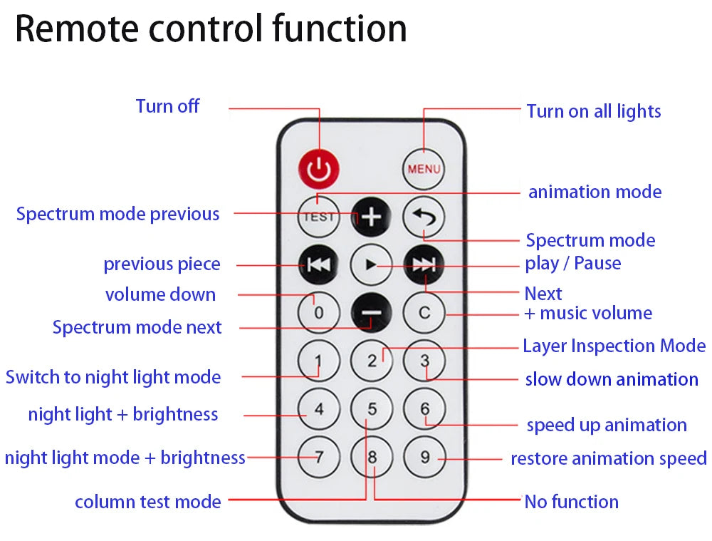
When the ir is down, the bump points forward through the gap, otherwise the remote control will not work
Because of transportation restrictions, the battery of the remote control may be removed before shipment, so make sure to install the battery before using the remote control
MIC Part of the distance from the PCB to facilitate the soldering of the LED behind
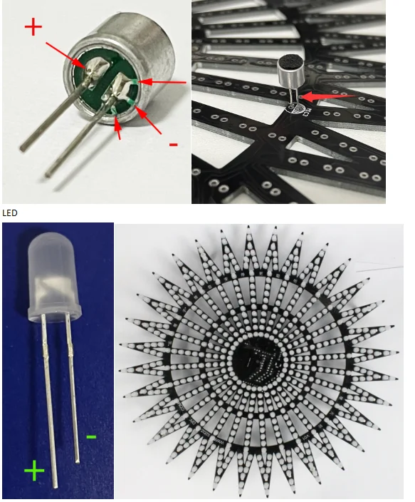
After the LED is welded, power on 5V 2A to test the PCB lamp board (note that 12V cannot be used!)
press 2 enter test mode,press+ to test each Each arrow,Make sure that all lights are on, and re-weld if any lights are not on
press 5 test each ring of the led, if all leds are working, then you can do nest steps.
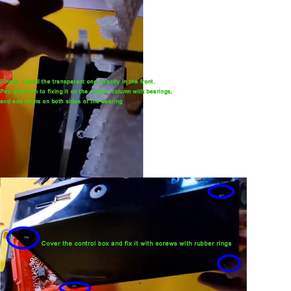
 To install the chassis, please scan the QR code video in the instructions inside the package for detailed instructions
also Check the wiring instructions at the following picture


We only sell the kits after rigorous testing, so the circuit and quality can be assured. The problems are usually in the production process, so we recommend you to check our tutorials more carefully, especially if some are noted. Place for details
1. Static inspection (no power-on inspection): correct installation, no wrong insertion of components, no false welding, no welding copper skin peeling and continuous welding.
2. Power-on test: 5v 2a power input test,with remote control press 2,5,8 test the led,if there any led not lighting, check the soldering point. check it full connect or not connect to other point.The input voltage must be within the range of the circuit requirements, and the power supply voltage must not be too high, which may cause the product to burn out! Connect to the normal working voltage, and then test whether all functions are normal according to the product function. If it is normal, the production is successful. If it is not normal, then look back at the schematic diagram and refer to the tutorial to detect welding problems.


